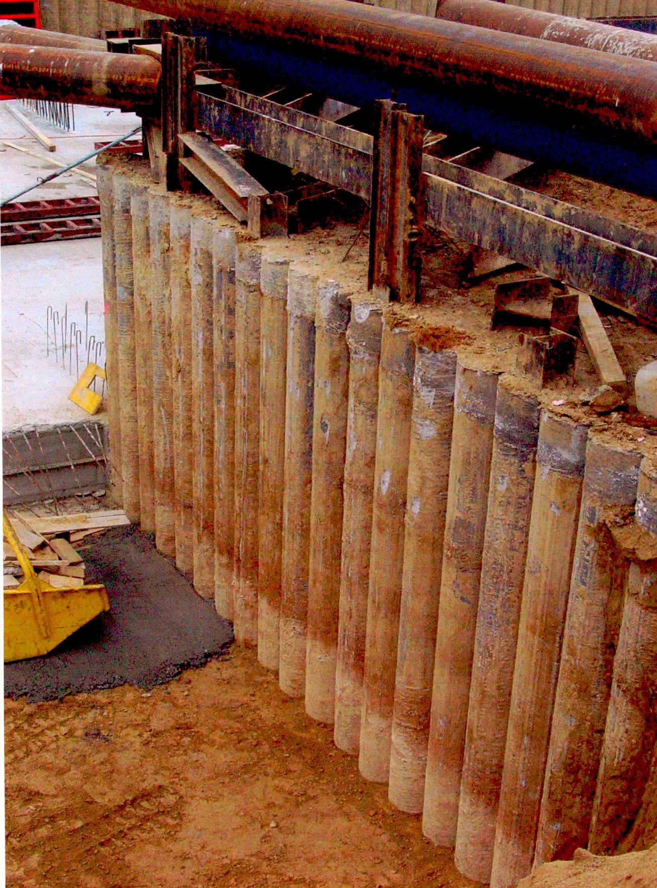
Bored Piles
Bored piles are typically high-capacity cast-in-place deep foundation elements constructed using different machinations of auger types and diameters. Once the diameter of a pile is designed, a hole or shaft is drilled to the design depth. In principal a very simple process, however it is common for site specific issues to add complications, as one example collapsing ground.
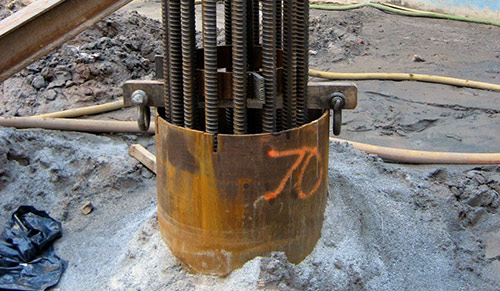
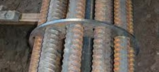
If a bored hole requires intervention to remain open a steel casing is often required so that the design requirements of a pile can be achieved. It is also common for the utilisation of drilling fluids to further aid hole support and or flush impurities out of the bored hole.
Once a bored pile design diameter and depth has been achieved steel reinforcing is lowered into the hole and the hole is filled with grout or concrete. The finished foundation element resists compressive, uplift and lateral loads. Bored piles are the most widely utilised foundation and have been utilised to support a myriad of construction projects from conventional buildings and towers to highways and bridges.
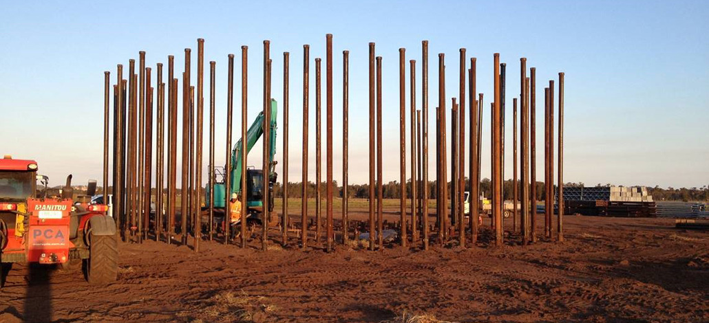
 PCA delivering a design and construct bored piles solution at the Macquarie University in Sydney NSW
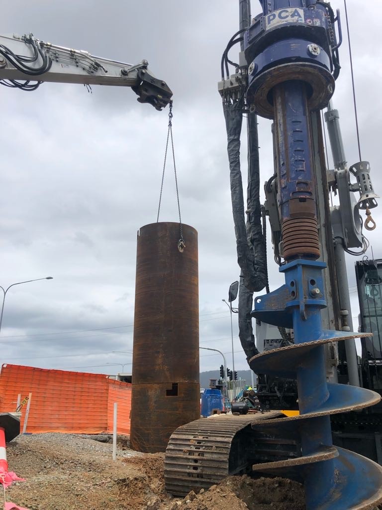
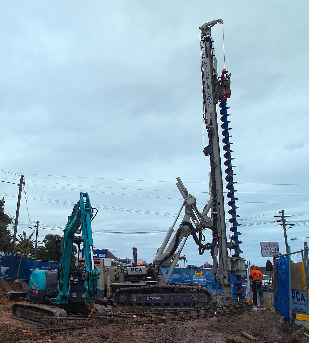
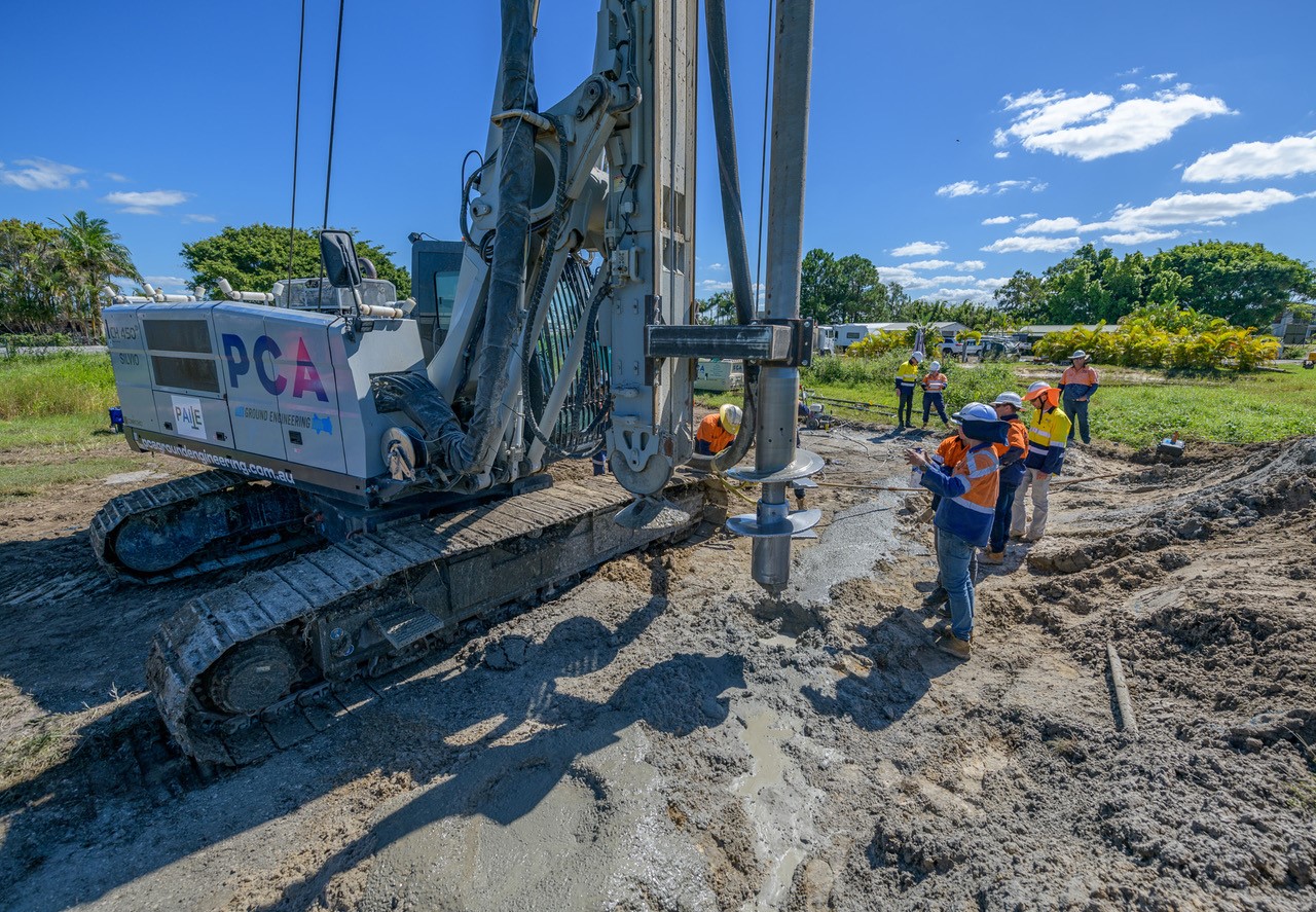
Continuous Flight Auger
 The continuous flight auger (CFA) piles were developed approximately fifty years ago and is one of the more common piling techniques, as they can be an economical solution to other piling systems in the right stratum. With effective planning and design, efficient equipment and experienced personnel, high production rates can be achieved.
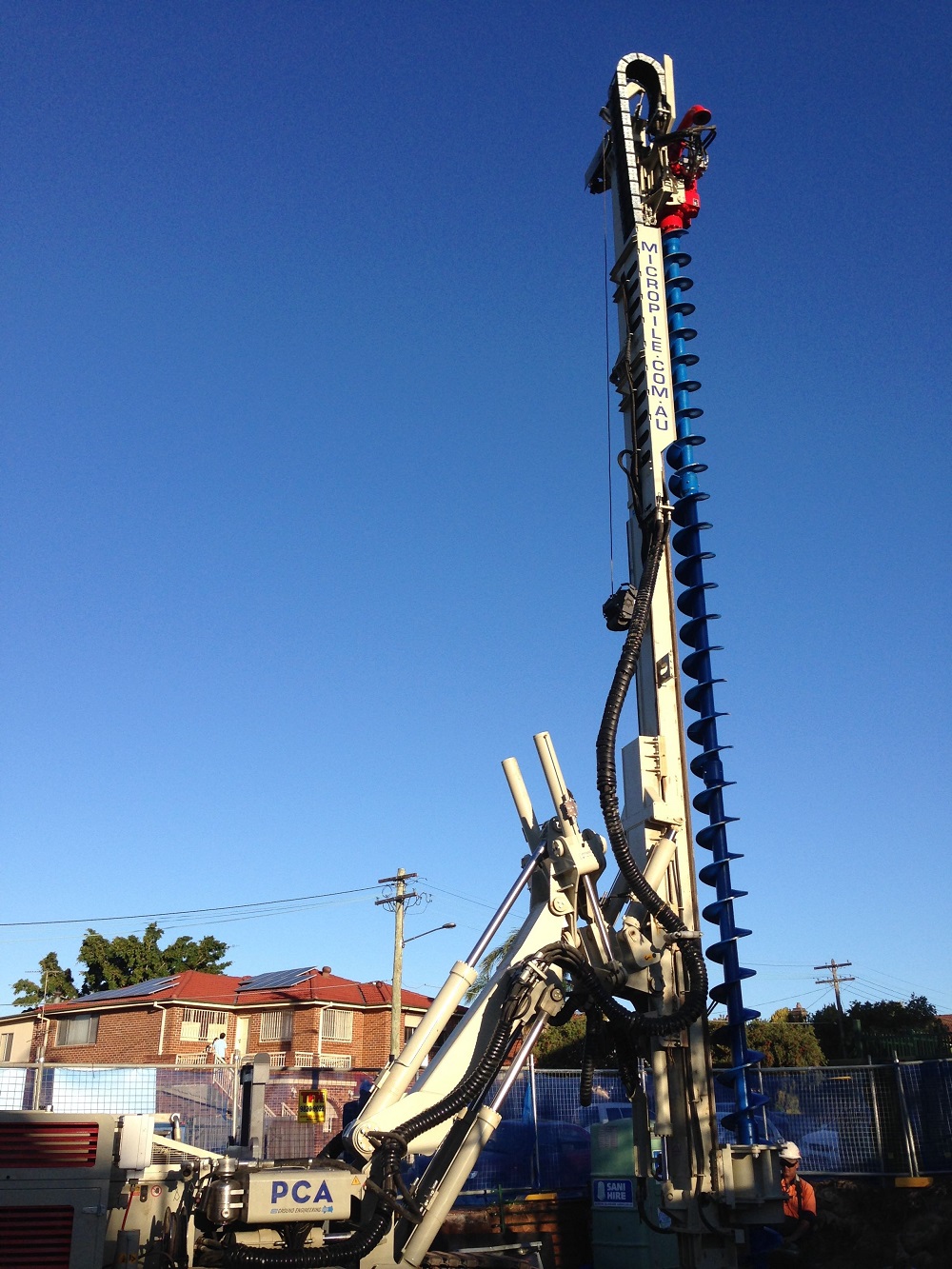 CFA piles are formed by drilling a continuous flight auger into the ground. The sides of the hole are supported at all times by the soil-filled auger, eliminating the need for temporary casing or bentonite slurry. Once the auger reaches the required design depth a temporary plug which prevents soil from entering the hollow stem of the auger, has to be ejected. Slightly lifting the auger and injecting the concrete or cement grout down the hollow stem of the auger with enough pressure to eject the plug allows the concrete or grout to flow freely. In a concurrent process with the concrete being pumped in to the pile, the auger is steadily withdrawn until the auger is completely removed from the pile. Immediately after withdrawal of the auger a reinforcing cage is placed into the grouted column concluding the production of a CFA pile.
The most common size CFA piles are 0.3, 0.45, 0.6, and 0.75 m diameter, with larger sizes by exception. They can be constructed to depths in excess of 30 meters.
An important feature of present day CFA piles is the use of a reliable flow meter to monitor and record the whole process of construction of this type of pile. The items recorded are usually penetration / uplift per revolution, auger depth, concrete supply per increment of auger uplift during placing, and injection pressure at the auger head.
In line with our continual pursuit of Worlds Best Practice, PCA are proud to be able to deliver a new adaptation to the traditional CFA pile referred to as the VDW system. It is a vibration free and low noise procedure used for installation of single piles, as well as contiguous or secant pile walls.
The process is very similar to that described above, however this system turns the auger and an outside casing simultaneously in a counter rotating directions. The spoil is ejected by openings at the upper end of the casing. The pile is filled with concrete, which is pumped by a separate concrete pump through the swivel of the auger head.
The auger head and the casing are pulled simultaneously during the grouting or concreting process. The result is a better connection to the adjacent soil and a significantly higher quality of finish, which can yield significant financial advantage when utilized as a finished basement wall in a car park or similar.
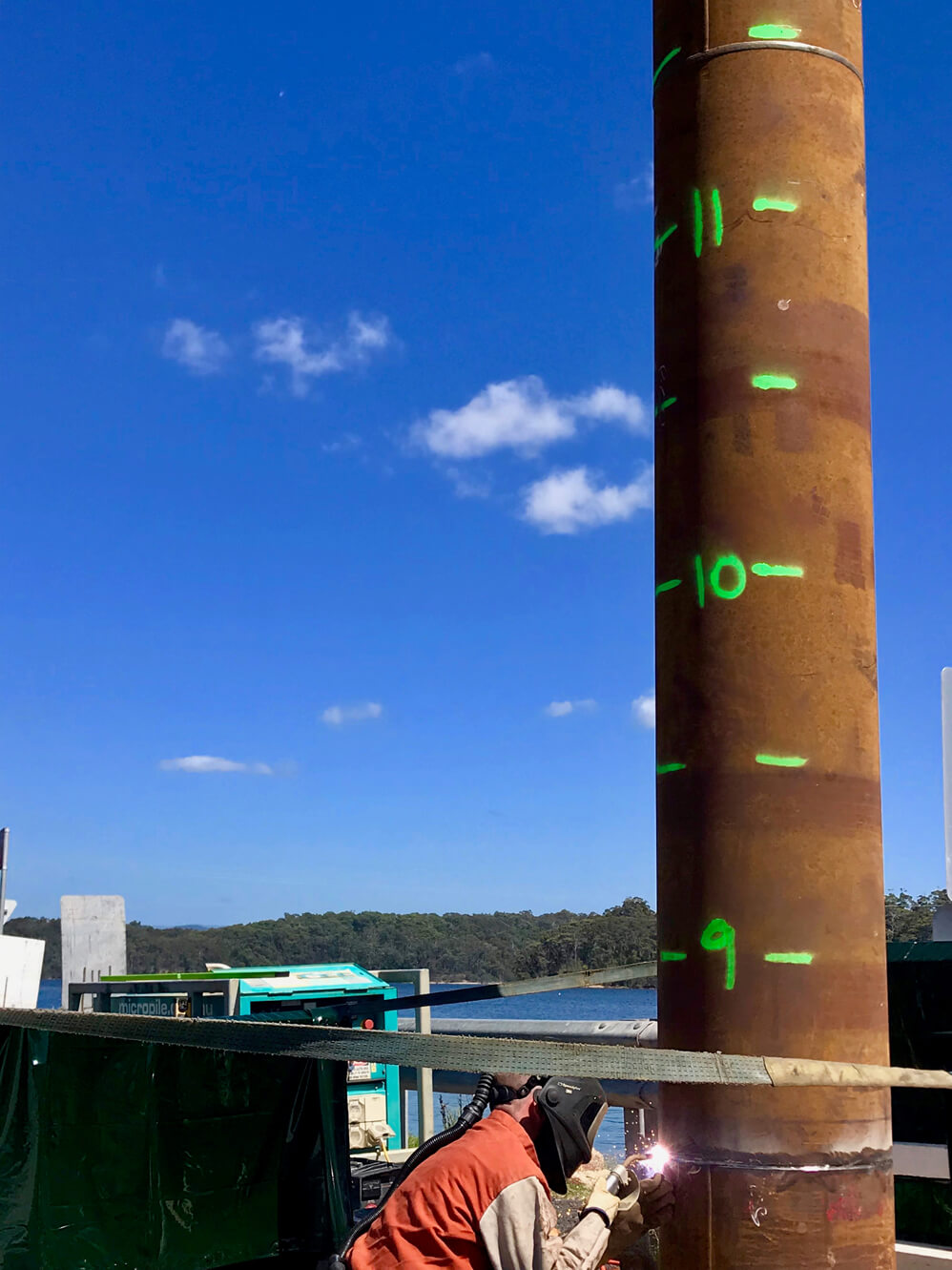
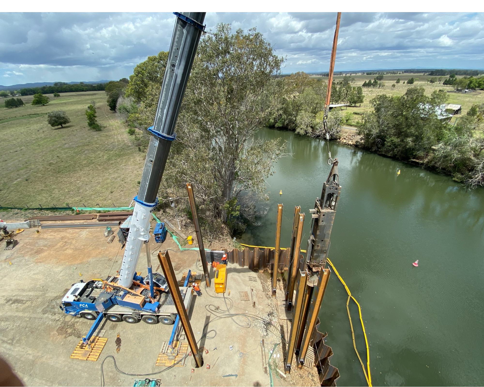
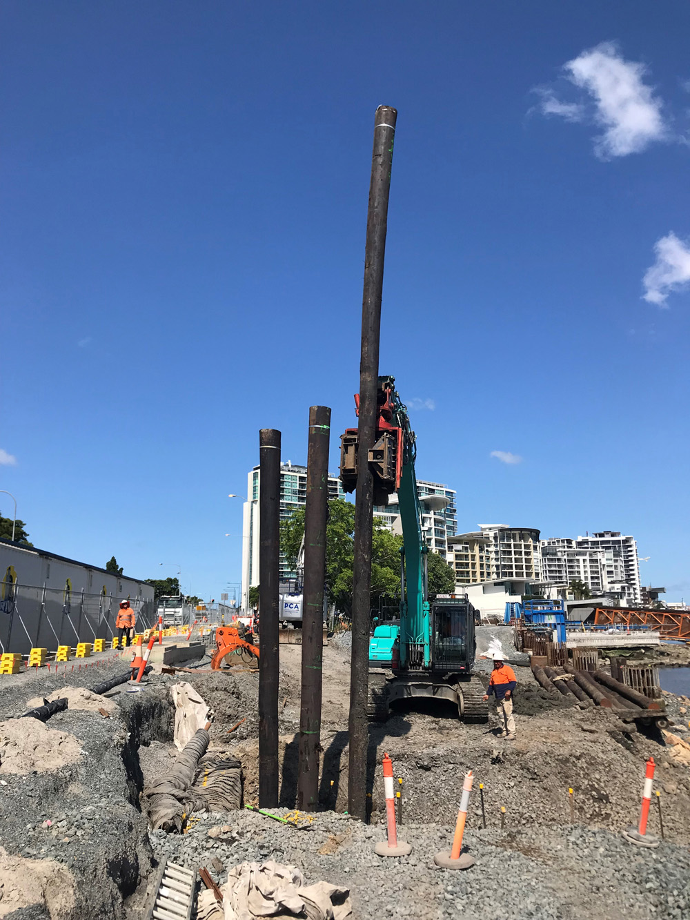
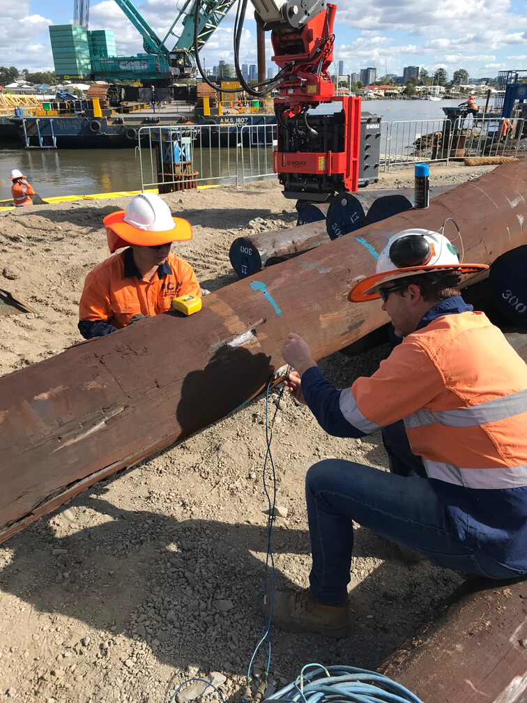
Driven Steel
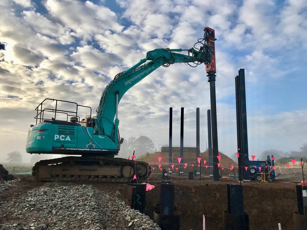
Driven steel piles are foundation elements driven to a design depth or resistance. Driven piles have been around for centuries and various products are utilized such as timber, steel and concrete and more recently composite materials specifically suited to estuarine and marine environments. Driven steel piles are suitable for taking compression, tension and lateral loads. The technique has been routinely utilized in commercial construction around the world.
Driven piles are ideally suited for use in locations where neighbouring structures will not be affected by vibration and noise. If penetration of dense soil is required, pre-drilling may be required for the pile to penetrate to the required design depth. To manage some of these risks, PCA has introduced equipment with new capabilities, which can install small to medium capacity driven steel piles with negligible vibration at nearly any rake angle.
PCA have accredited welding professionals to deliver the highest required standards essential to installing driven steel piles.
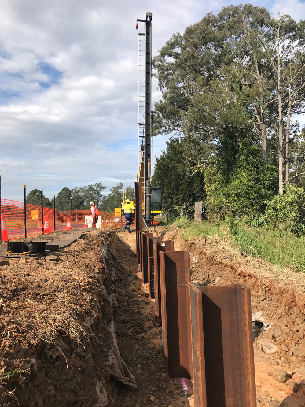 PCA installing “I” Beams for a retaining wall at a Roads and Maritime Site
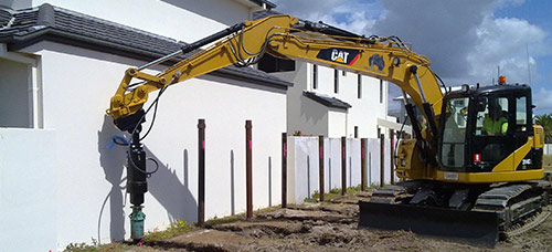
Mini Caisson Piles
 Mini Caisson Piles are designed for deep foundation projects typically utilized in densely populated or heavily congested environments where other piling methods cannot be effectively delivered. Mini Caisson Piles share many similarities with large capacity micropiles however the casing size is larger, between 300-400mm. The caisson or casing can be utilized as reinforcing component of the pile or a combination of casing and high strength reinforcing bar is utilized depending on the load requirement from the pile. Mini caisson piles can be installed through almost any type of subsurface condition from sands to clay to bouldery soils and solid rock. Piles socketed into rock or bearing on rock, are capable of carrying more substantial loads than piles relying on skin friction values. Caisson piles can be installed in confined space and low headroom situations. Low-vibratory drilling techniques ensure minimal disruption to the surrounding area and load transfer can be achieved without disturbing underlying structures.
Mini caissons can be installed through almost any subsurface and are ideal for projects with minimal work space and low headroom. Mini caissons are capable of handling larger loads than standard micro piles.
Mini Jet Piles
 The mini jet piling technique utilises high pressure grouting technology to significantly increase the effective diameter of pile as the bar is jetted into the soil. Mini jet or high grout pressure piles have two areas of advantage over grouted earth blocks or micropiles.
Conventional hollow bar micropiles are usually injected with grout at a moderate pressure, generally in a range between 10-25 bar and at this pressure produce a grout annulus (grouted body) that is marginally in excess of the bit diameter. Some projects require piles that manage more substantial compressive or lateral loads which can only be achieved by larger grout columns, this is where mini jet piles can be a valuable and viable solution.
The second area where a mini jet pile can provide advantage is where a foundation remediation requires grout injection or the creation of a grouted soil block and piling (a dual process). The utilisation of mini jet piles in a single process can both create a grouted soil block and the pile capable of resisting lateral and/or vertical stresses, which can provide significant time and cost savings.
High pressure and mini/jet grouted piles are a reliable and effective piling solution in lower end DCP geotechnical conditions, however they do require the skills of a competent contractor and modern equipment that provides real time data and measurement to ensure that the design criteria and pile dimensions are achieved.
Screw Piles
 Screw Piles also known as helical piles, are constructed using steel shafts with helical flights. The shafts are advanced to bearing depth by twisting them into the soil while monitoring torque to estimate the pile capacity. A thorough understanding of the subsurface conditions is necessary to properly interpret the torque conversion.
PCA utilise NATA certified load cells to ensure that piles are installed in kilo newton’s to the engineers design requirement. Installing screw piles with a sound understanding of the underlying stratum is essential as screw piles are an end bearing pile and cannot adequately perform without the helix being installed in a soil layer capable of bearing the design load.
After reaching design capacity and depth, the tops of the shafts are cut utilising oxyacetylene to the required RL. Screw piles are generally connected to the main structure via a pile cap however they can also be directly connected to structures such as demountable housing or utilised for underpinning, bracketed to a structure’s footing to stop settlement. Insist your screw pile contractor installs screw piles with a calibrated load cell
There are significant production and engineering advantages of using a calibrated load cell to measure accurately the installation of screw piles;
- Actually measures torque, not the hydraulic line pressures which can fluctuate.
- Reduces the risk of exceeding the structural capability of the pile (pipe)
- Easy for operator to use- only one gauge to monitor
- False readings or subsurface concerns are obvious to operator as shows as an error on digital readout
- Engineers can be provided installation records in kilo newton’s, not PSI requiring conversion tables and assumptions
- Accurate and repeatable every time
- World best practice for screw pile installation
Underpinning
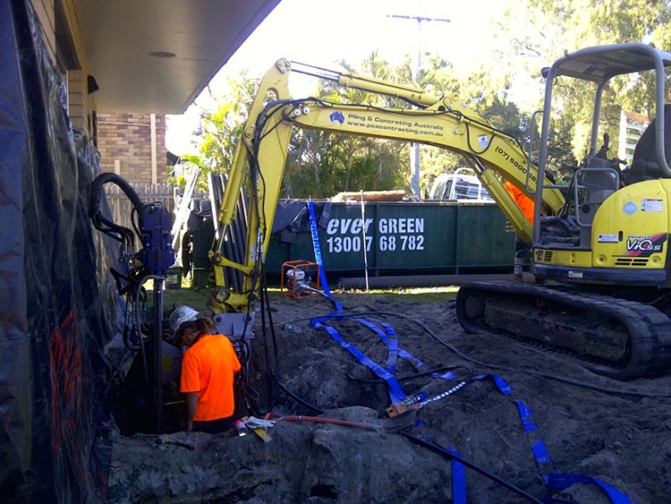 Underpinning describes the process of improving or increasing the capacity of an existing structures foundation. This can be achieved by the introduction of grout or more commonly by extending the foundation in depth, typically by the introduction of piles so a structure is supported on a more supportive stratum.
Underpinning of a structure maybe required for numerous reasons;
- Failure of the original foundation.
- Change in use of a structure, such as adding levels.
- To protect existing structures immediately adjacent to new construction and excavation.
- Environmental changes such as flood or drought can cause a structure to move.
- Siesmic events such as earthquake can necessitate underpinning.
There are a myriad of different techniques to underpin structures however the use of micropiles and/or high pressure grouting are very effective methods from a capability and cost perspective. Technological advancements in micropiles provides new opportunities in underpinning in both small and very large projects. Piles are installed to a bearing depth and then the tops of the piles are connected to the structure’s existing foundation. Once this underpinning connection is achieved a structures settlement is arrested. Alternatively at this stage a structure can also be raised by the application of hydraulic jacks. This process provides an additional benefit of confirmatory load testing, as each pile is proven to work as a structure is carefully raised. The finished piles stop settlement and can raise a structure that has subsided, closing cracks and correcting other structural flaws.
There are numerous case studies available for the underpinning of large-scale infrastructure, commercial and historical projects utilising micropiles. One of the more grand examples of this was undertaken at the Arenas de Barcelona. A new commercial center was constructed with underground parking within the historic façade of Barcelonas main bull ring. This incredible project provided the opportunity to preserve an historic structure and utilize valuable land simultaneously. This project demonstrates that with the use of micropiles what was once an inconceivable construction process is now feasible from both a construction and development perspective.
Timber Piles
PAILE Foundation & Ground Improvement System
PAILE is a foundation and ground improvement system which in its properties resembles a standard concrete pile with enlarged base.
However, the technology used to construct PAILEs allows for:
- Increased efficiency – Halve the material usage, carbon footprint, mobilization cost and time it takes to install a concrete pile
- Simpler logistics – Requiring small equipment, there’s no site preparation, temporary works requirement, vibration, disturbance or heave
- Lower risk – Instant static tests lower risk, allow for on-site depth adjustment
During the base forming phase, the bottom helix displaces and compacts soil underneath the pile base. This process effectively preloads the base of a pile which leads to improved subsequent load/settlement performance and provides verification of pile end bearing capacity. Enlarged pile base enables significant optimisation of pile volume, which leads to material cost savings and reduced carbon footprint.
The method facilitates the installation of a pile with an enlarged and prestressed base in a single continuous process, using comparatively lightweight and manoeuvrable equipment when compared to traditional piling techniques. In addition, during formation of the enlarged base the geotechnical capacity of the base is verified and recorded, allowing instant pile depth adjustment in response to changing ground conditions.
PCA Ground Engineering is pioneering the PAILE technology and has the widest experience in the technology thus far.
Micropiling
See main micropiling page. Click here.